RcBuildingCreateFromRoofPrint
| Command Name | Icon | Menu Path |
|---|---|---|
| RcBuildingCreateFromRoofPrint | Not yet in menu (CLI only) |
Overview
This command processes roof geometry for the 3D modeler.
Prerequisites
Requires closed 3D roof curves.
Input curves can be either attributed or raw geometry.
Attribute Management
Building Grouping: If attributes are present, a common identifier (e.g., Building ID) is used to group multiple roof parts. This value is mapped to the
BuildingIDproperty in the modeler classes.Elevation (ZMin): An optional attribute can define the
building’building's base altitude. If provided, generated Roofprint curves are set to this Z-value; otherwise, they are created at Z = 0.0.
Grouping for Raw Geometry
If the input curves lack attributes, they must be pre-grouped. The command uses Rhino Group membership to
associateidentifydifferentbuildingroof elements with their respective building.
Output Options
Users can choose to either transform the original curves or duplicate them to create new entities compatible with the 3D modeler.
Workflow
Step 1: Initial Options
When launching the command, the first prompt defines the generation logic:
RoofPrintLayer: Select the source layercontaining the roof curves(e.g., 'Roofs1').ComputeConstrId(yes/no):Defines ifInitialize theConstrIDattribute should be initialized.attribute. Recommended: yes.OriginalCurves(duplicate/modify):Duplicate
:Creates new entities for the modeler while preservingpreserves source geometry.(Preferred)Modify: Transforms original curves directly into modeler objects.
Step 2: Attribute Mapping
The second prompt defines how buildingthe data is structured:structure:
BuildingID:
FallsSelect theGrouping attributeused to group separate roof parts into a single building(e.g.,selecting the'id').attribute).If undefined:The command will fallbackback to Rhino Groupstoifidentify building units.
ZMin:
Select theElevation attributedefining the base altitude of the building(e.g., 'r_zminid').If undefined:Roofprintcurves are createdCreated at Z=0.0.if
Step 3: Execution & Selection
Review the summary displayed in the command line.
Select curves: Pick specific curves or hit
[Enter]to process allobjects on the selected layer.
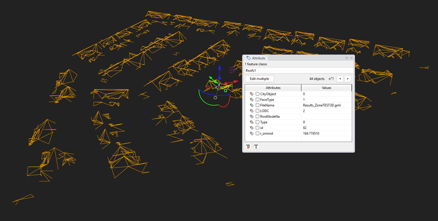
Example
OnceIn processed,this example, we use roof curves from a Shapefile (3D Polygons) in the CLI'Roof1' confirmsclass.
Upon launch, the creationcommand line displays:
Options (RoofPrintLayer=nolayer ComputeConstrId=true OriginalCurves=duplicate):
By clicking on the RoofprintLayer option, we select the “Roofs1” layer
Confirm our choices with [Enter]
The command line now displays:
Define the potential attributes (BuildingID=undefined ZMin=undefined):
By clicking on ‘BuildingID’, we select the ‘id’ attribute of the semantic‘Roof1’ structure:class
-
RoofprintAttribute to be used as “BuildingID” (CityObject FaceType FileName LODC RootNodeNa Type id r_zminid):&The command line changes to:
Define the potential attributes (BuildingID =id ZMin =missing):By clicking on ‘ZMin’, we select the ‘r_zminid’ attribute from the ‘Roof1’ class.
Confirm our selections with
Building[Enter]Upon launch, confirm your choices with
[Enter]. The CLI displays the selection details:• layer containing the roof curves: 'Roofs1'
• use attribute 'id' as a 'BuildingID'
• use attribute 'r_zminid' to fix the Z of the Footprint curvesNext, select the curves and press
[Enter]. The command line displays the final summary:• feature classesclasscreated."Roofprint" created ✔
• feature class "Building" created ✔
• load 2 feature classes: "Building", "Roofprint" loaded
• "Building", "Roofprint" objects stored
• 141 feature class "Building" items prepared
• 1930 feature class "Roofprint" items prepared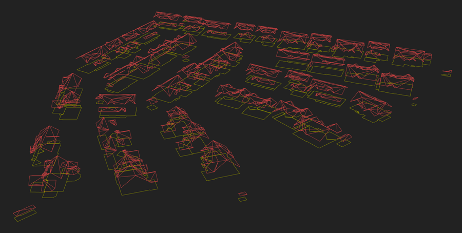
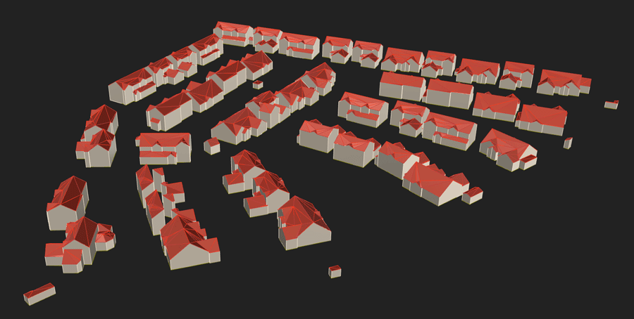
Objects stored and mapped with their respective IDs.Ready for modeling:you can now proceed to the 3D generation.success:
(ツ)Success:Youyou can now use theRcBuildingModelerModelize command to create 3D buildings!command!
Here
is the result after modelling